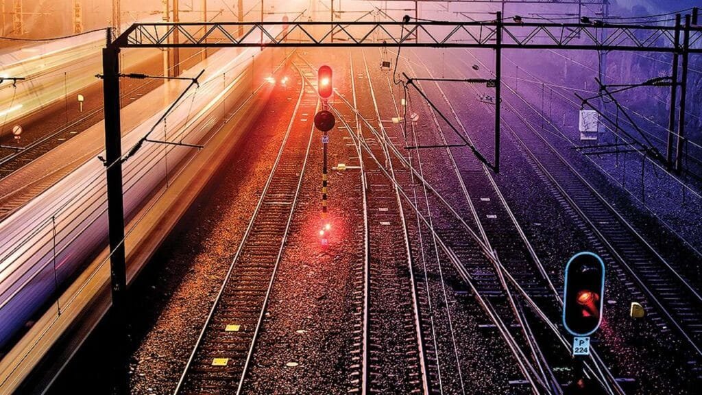

Switches Aligned, Route Clear!
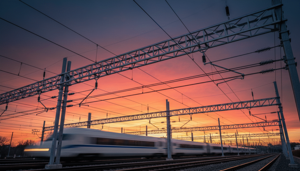
At 300 km/h, the pantograph barely touches the wire. A carbon strip skimming a copper alloy cable, drawing 10 megawatts of power from the sky. That cable carries 25,000 volts—standard voltage, familiar to any railway engineer. But beside it runs a second wire, invisible to passengers, carrying the opposite polarity. Between them: 50,000 volts of electrical potential that makes the whole system work.
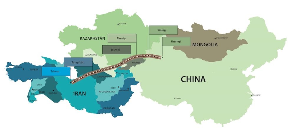
This is the 2×25 kV autotransformer system, the invisible architecture behind every high-speed line from Milan to Madrid, from Paris to Beijing. The train still operates at 25 kV, but the supply infrastructure works differently—creating a circuit that defies intuition and enables speed.
But why the second wire? How does adding a feeder at −25 kV change the physics of power transmission? And why does this system dominate high-speed rail while standard 25 kV remains the choice for regional networks?
The Distance Problem
Standard 25 kV AC electrification works well for regional trains. A locomotive draws power from the contact wire, current flows through the motors, and returns to the substation via the running rails. Over 30 or 40 kilometers, this works fine. The rails—solid steel, not copper—offer resistance, but the distances are short enough that voltage drops remain manageable.
High-speed rail breaks this model. A train from Milan to Rome covers 300 kilometers without stopping. A Beijing-Shanghai train travels 1,300 kilometers at 350 km/h. At these distances, the resistance of steel rails becomes a wall. The current needed to accelerate 400 tonnes to 300 km/h—thousands of amperes—creates voltage drops that would require substations every 30 kilometers. The infrastructure cost would be enormous; the complexity, unsustainable.
The solution is not more substations. It is a different way of moving current—and a trick of electrical engineering borrowed from power utilities.
The Autotransformer Trick
The 2×25 kV system uses geometry to cheat resistance. The contact wire carries about +25 kV relative to the rails. A parallel feeder wire, suspended above or beside it, carries −25 kV. Between them: 50,000 volts of potential difference. But the train still draws only 25 kV from the contact wire.
Here is the innovation. The return current no longer relies mainly on the rails alone. Instead, the feeder wire and autotransformers provide a much lower-impedance return path, so the rails carry only part of the return current, rather than serving as the primary return path.
Every 10-15 kilometers, an autotransformer—a special transformer with a single tapped winding—connects catenary, feeder, and rails. The result is a dramatic reduction in resistive losses. The current flows in a balanced loop rather than seeking ground through steel. Substations can be spaced 60-80 kilometers apart, sometimes more, reducing the number of major feeding points needed along the line.
Why the Dual-Voltage Approach?
Voltage is the pressure of electricity. To deliver the same power, higher voltage means lower current, and lower current means less heat lost in the wires. This is why national power grids use 400 kV for long-distance transmission.
But railway catenaries cannot safely operate at 400 kV—the clearance requirements, insulation, and safety margins would make the overhead line impossibly bulky. The 2×25 kV system achieves similar benefits differently: by creating a 50 kV potential between two supply conductors while keeping each conductor at a manageable 25 kV relative to the rails.
The trade-off is complexity. The system requires that second wire, the feeder, running parallel to the catenary for the entire line length. It requires autotransformer stations—shed-sized buildings every 10-15 km—housing transformers that must be maintained and cooled. And it requires sophisticated protection systems, because higher voltages involve larger power flows that demand faster, more sensitive fault detection.
Where the System Lives
Many high-speed networks—including those in Italy, France, Spain and China—use 2×25 kV or closely related autotransformer feeding arrangements. Japan also uses autotransformer-based 25 kV feeding on many Shinkansen lines. In contrast, Germany’s ICE network uses 15 kV at 16.7 Hz—a legacy of early electrification that complicates interoperability but remains entrenched. The UK and Scandinavia largely use standard 25 kV, accepting the limitations for historical compatibility.
For many new high-speed lines, especially where power demand and distance are high, 2×25 kV has become the preferred solution. For legacy networks upgrading from older DC systems—like Italy’s former 3 kV lines or the UK’s third rail—the decision is harder: the cost of converting to autotransformer systems versus the benefits of compatibility with existing rolling stock.
The Maintenance Reality
The autotransformer stations require monitoring: transformer condition, cooling systems, insulation health and protection equipment. High-voltage insulation remains a major maintenance concern, especially in polluted or coastal environments.
But the benefits persist. The reduced current in the rails means less electrolytic corrosion of track hardware. The fewer substations mean fewer points of failure. And the ability to push roughly 8-12 megawatts to a single train—enough to sustain high speeds under heavy power demand—makes the complexity worthwhile.
Conclusion: The Invisible Upgrade
Passengers never see the second wire. They do not notice the autotransformer sheds blurring past at 300 km/h. They simply experience the result: a train that accelerates without hesitation, that maintains speed on hills, that does not slow down for power limitations.
The 2×25 kV system is a lesson in engineering trade-offs. It adds complexity to the infrastructure to reduce complexity in operation. It demands higher initial investment for lower lifecycle costs. And it represents the difference between a railway that moves trains, and a railway that moves them fast.
Stay with Beyond Tracks as we continue exploring the invisible systems that make high-speed rail possible—from the wire above to the rails below, and the physics that binds them.